Draw Bench Conveyor Chain
Configure replacement and new-build chain around your bench pull requirement, pitch, sidebar geometry, pin arrangement, sprocket interface and operating environment.
Product Series
Browse the populated WooCommerce product families below. Every published product has a verified project image; unsupported numerical ratings are withheld until drawing confirmation.
Chain Components
Pins, plates, bushes, connecting elements and maintenance spares tied to approved chain drawings.
View Products →Draw Bench Chains
Engineered-to-RFQ draw bench chain families for pulling and replacement duties.
View Products →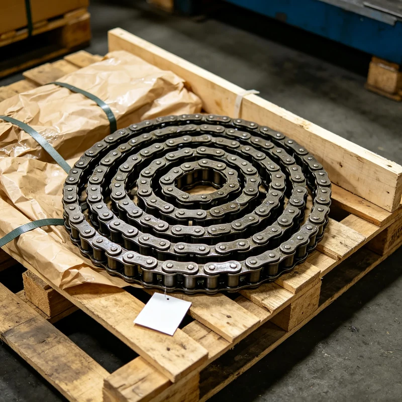
Draw Bench Conveyor Chains
Primary draw-bench chain family for drawing-based new-build and replacement projects.
View Products →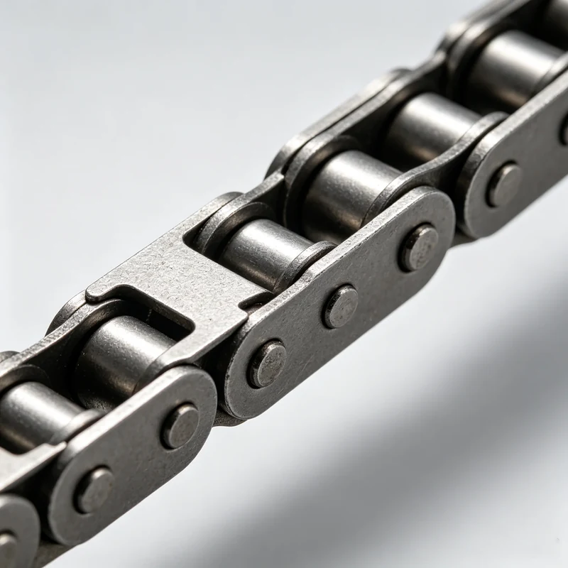
Related Conveyor Chain Configurations
Related conveyor-chain configurations documented by the supplied media set.
View Products →Sprockets & Accessories
Matched sprocket and chain-interface components for draw bench systems.
View Products →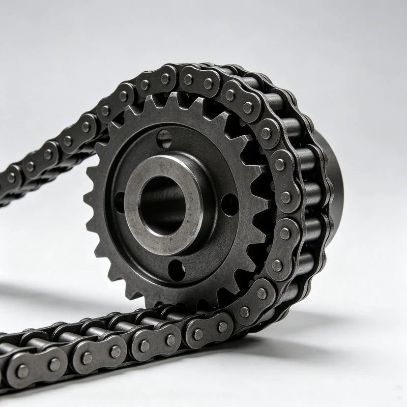
Sprockets And Components
Chain sprocket assemblies and replacement components requiring geometry confirmation.
View Products →Engineering Advantages
Drawing First
Selection starts from the chain path, pitch, cross-section, pin details, sprocket relationship and bench duty rather than a guessed model number.
Replacement Matching
Photos, worn samples and old drawings can be organized into a replacement-identification workflow before final manufacturing data is released.
Evidence Boundaries
Market references are used for terminology and buyer questions only. Project specifications remain subject to documented confirmation.
Typical Applications
Draw bench chain is an engineered-chain category associated with high-tension pulling duties in tube and metalworking lines. Related conveyor chain configurations can also support positioning, transfer and material handling when their geometry and duty are appropriate.
- Tube and bar drawing equipment
- Steel and metal processing lines
- High-tension sliding chain systems
- Industrial conveying and transfer
- Replacement chain and sprocket projects
Operating Principle
The chain transfers pulling force from the drive and sprocket system to the moving draw-bench carriage or connected load. Chain pitch, sidebar form, pin retention, length, sprocket engagement and the bench duty cycle work together as a system.
For replacement work, do not select from appearance alone. A drawing or measured sample should confirm the load path and mating geometry.
Customization Options
Geometry
Pitch, inner width, plate profile, thickness, pin diameter and pin length are project-defined inputs.
Interfaces
Specify attachment points, end connections, carriage interfaces and matching sprocket details where applicable.
Service Conditions
Provide pull force, shock loading, speed, duty cycle, lubrication, contamination and temperature information for engineering review.
Key Parameter Range
| Parameter | Website Publication Status | RFQ Input |
|---|---|---|
| Pitch | Project-specific; not published without evidence | Measured pitch or drawing |
| Inner width | Project-specific | Measure between sidebars |
| Sidebar height / thickness | Project-specific | Drawing or sample |
| Pin diameter / length | Project-specific | Drawing or sample |
| Required pull / working load | Project-specific | Bench requirement |
| Material / heat treatment | Confirm during engineering review | Environment and duty |
| Sprocket interface | Confirm with chain geometry | Tooth count and drawing preferred |
Selection Guide
Identify The Bench
Share machine type, chain path, carriage arrangement and available drawing.
Measure The Chain
Record pitch, widths, plate dimensions, pins, overall length and connection details.
Confirm The Duty
Provide pull force, operating speed, duty cycle, shock behavior and environment.
Verify The Sprocket
Include sprocket tooth count, width and available dimensions or photographs.
Technical Support
Presales
Clarify application scope and the data required for a useful quotation.
Technical
Review dimensions, chain path and mating interfaces before specification freeze.
Customization
Organize non-standard chain and sprocket requirements around controlled drawings.
After-Sales
Use inspection photos and dimensional records to support replacement decisions.
Prepare Your RFQ
Send the bench drawing, old chain dimensions, required quantity, pull/load information and available sprocket data. If some values are unknown, mark them as unknown instead of estimating.